
Why Does Ground Wire Selection Decide Safety, Reliability, and Noise Performance?
Abstract
A ground wire is easy to overlook until something goes wrong: unexpected equipment resets, interference that ruins signals, tingling enclosures, failed inspections, or (worst case) shock and fire risk. This guide breaks down how ground wires actually work in real systems, what typically causes grounding problems, and how to choose a ground wire that fits your electrical, mechanical, and environmental constraints. Along the way, you’ll get practical checklists, a comparison table of common grounding conductors, and field-proven installation tips. If you’re evaluating braided grounding products or building a grounding strategy for a machine, panel, vehicle, or enclosure, you’ll leave with clear next steps. For manufacturers and project teams, Dongguan Quande Electronics Co.,Ltd. supports grounding conductor selection and customization so your design performs consistently from prototype to production.
Table of Contents
- Outline
- What a Ground Wire Actually Does
- Customer Pain Points Grounding Issues Create
- How to Choose the Right Ground Wire
- Common Grounding Conductor Types and When to Use Them
- Sizing Considerations That Prevent Surprise Failures
- Installation Practices That Make or Break Grounding
- Common Mistakes and How to Avoid Them
- How to Verify Grounding Quality in the Field
- FAQ
- Next Steps
Outline
- Ground wire purpose in safety and signal integrity
- Symptoms of poor grounding and why they happen
- Selection framework covering electrical load, frequency behavior, and environment
- Comparison of braided straps, stranded wires, and busbars
- Installation details that reduce resistance and prevent loosening
- Verification methods and practical acceptance checks
- FAQ and sourcing guidance
What a Ground Wire Actually Does
The phrase “ground wire” gets used for multiple jobs, and mixing them up is where many projects get into trouble. In most applications, a ground wire supports one or more of these functions:
- Safety fault path: If a live conductor contacts a metal enclosure, the ground path helps carry fault current so protection devices can trip quickly.
- Equipotential bonding: Connecting metal parts so they stay at nearly the same potential reduces touch voltage and minimizes arcing risk.
- Noise control and reference stability: A good ground connection can reduce electromagnetic interference by providing a controlled return path and lowering impedance at relevant frequencies.
- Lightning and surge diversion: In some systems, grounding conductors help route high-energy transients safely (often as part of a broader bonding and surge strategy).
Notice the word impedance, not only resistance. Many grounding problems show up at higher frequencies where a conductor that looks “fine” on a basic meter still behaves poorly due to inductance, length, and connection geometry. That’s why the physical shape of a grounding conductor can matter as much as its cross-sectional area.
Customer Pain Points Grounding Issues Create
If you’ve ever had a system pass a bench test but fail in a factory, vehicle, or outdoor installation, grounding is often part of the story. Here are the most common customer pain points we see across industrial and electronic systems:
- Random resets and unexplained faults: Intermittent grounding connections can create voltage shifts that confuse control electronics.
- EMI that won’t go away: Shielding and filters can’t fully compensate for a poor return path or high-impedance bonding between enclosures.
- Failed inspections or compliance delays: Inadequate bonding, incorrect terminations, or poor documentation can lead to rework and schedule slip.
- Overheating at connection points: A “small” contact issue becomes a hot spot under fault current or repeated surge conditions.
- Corrosion and loosening: Outdoor, marine, humid, or chemical environments can degrade connections faster than teams expect.
- Assembly headaches: Wires that are too stiff, too short, or prone to fatigue can make production inconsistent.
The good news is that most of these are preventable. The key is treating grounding as a mechanical-and-electrical design problem, not an afterthought.
How to Choose the Right Ground Wire
A reliable selection process starts with your real constraints, not just a catalog description. Use this framework:
1) Define the grounding job
- Is it primarily safety bonding, noise control, surge handling, or a combination?
- Is it enclosure-to-enclosure bonding, door bonding, panel bonding, or cable shield termination?
2) Map the electrical demands
- Fault current expectations: Protective device behavior depends on a low-impedance path.
- Frequency behavior: For noise and EMI, shorter and wider conductors often outperform longer, narrower ones.
- Duty cycle: Occasional surges are different from continuous current sharing.
3) Match the mechanical reality
- Will it flex (doors, hinges, vibration, robotics)? If yes, a flexible grounding conductor is critical.
- Is space tight? Is there a repeated bend radius requirement?
- Will installers have consistent access to torque fasteners properly?
4) Consider the environment
- Humidity, salt spray, chemicals, high temperature, UV exposure, or oil contamination can change material choices.
- If corrosion is likely, surface treatments and connection hardware matter as much as conductor material.
5) Decide on termination strategy early
- Ring terminals, lugs, weld tabs, stud connections, or clamp-style bonding each demand different conductor constructions.
- Consistency in termination equals consistency in performance.
If you want fewer surprises in production, lock these decisions before you finalize harness drawings. Dongguan Quande Electronics Co.,Ltd. often supports teams by confirming fit, flexibility, and termination compatibility before mass production.
Common Grounding Conductor Types and When to Use Them
| Type | Best For | Strengths | Watch Outs |
|---|---|---|---|
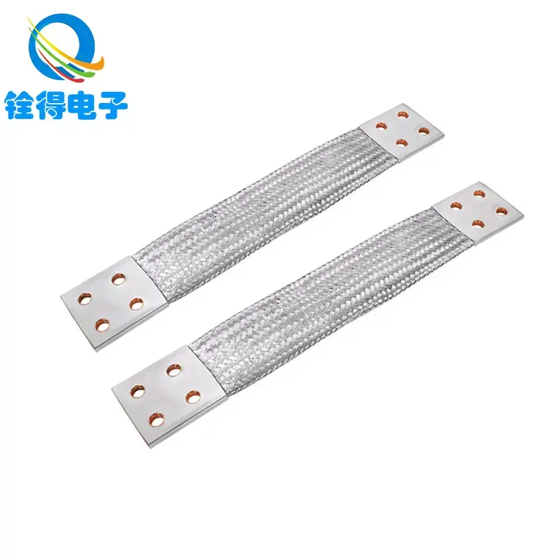
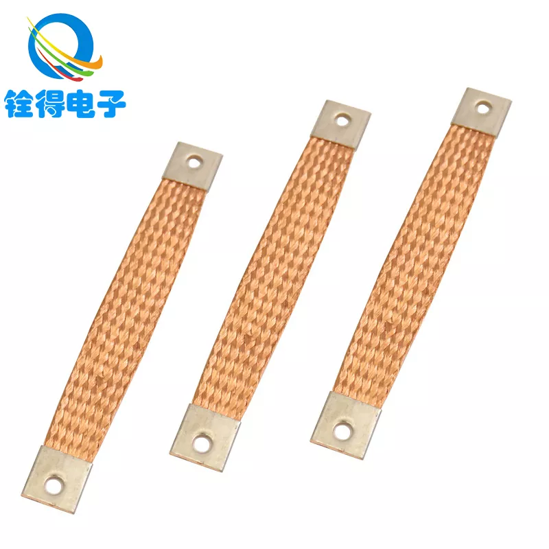
| Braided grounding strap | Bonding enclosures, doors, cabinets, EMI-focused bonding, vibration environments | Very flexible, low impedance geometry when kept short and wide, good for moving joints | Termination quality is everything, can corrode if not protected, needs proper strain relief |
| Stranded copper wire | General bonding, internal panel wiring, predictable routing | Easy to terminate, widely available, good current capacity for its size | Can be stiff in larger sizes, longer runs increase inductive impedance for noise control |
| Busbar or bonding bar | Panels and switchboards with multiple bonds | Repeatable connections, low resistance, tidy distribution | Not flexible, needs space, may not handle vibration without proper mounting |
| Shield termination clamp or braid pigtail approach | Cable shielding strategies | Clamps can provide 360-degree contact and strong shielding performance | Pigtails can degrade high-frequency shielding if too long; geometry matters |
For many industrial cabinets, the “best” choice is a combination: a bonding bar in the panel, short braided straps for doors and moving parts, and well-terminated stranded conductors for fixed connections.
Sizing Considerations That Prevent Surprise Failures
Sizing isn’t just “bigger is better.” Oversizing can create stiffness, assembly problems, and fatigue. Undersizing can overheat, fail protective device clearing, or create unstable references. Keep these principles in mind:
- Shorter beats thicker for many noise-related issues. Reducing length often improves performance more than increasing cross-section.
- Wider can beat round at higher frequencies. Flat braided straps can reduce impedance when installed properly.
- Connection area matters. A thick conductor on a tiny contact patch can still perform poorly.
- Thermal and fault events are different. A conductor can survive a short fault pulse yet fail under repeated surges or heating at a bad joint.
If your design must meet a particular electrical code or industry standard, use that standard’s sizing method as the baseline, then layer mechanical and environmental requirements on top. When in doubt, treat termination and mounting as first-class design items, not “installer details.”
Installation Practices That Make or Break Grounding
Most grounding failures happen at interfaces. The conductor is rarely the problem; the connection usually is. These practices dramatically improve outcomes:
Use clean metal-to-metal contact where bonding is required
- Remove paint, anodizing, or coatings at the bonding point unless the hardware is designed to pierce coatings reliably.
- Use appropriate washers or bonding hardware to maintain contact pressure over time.
Control loosening under vibration
- Use locking methods compatible with your hardware and environment.
- Apply consistent torque and document it for production.
Minimize length and avoid loops
- Route ground conductors as short and direct as possible.
- Avoid large loops that can pick up interference like an antenna.
Design for movement instead of hoping it won’t move
- For doors, hinges, and vibrating assemblies, a braided ground strap with proper strain relief often outlasts a rigid wire.
- Respect bend radius and ensure the strap or wire isn’t the mechanical stop.
Standardize terminations
- Choose a termination style and apply it consistently across builds.
- Crimp quality, lug fit, and contact surface preparation should be controlled processes.
Common Mistakes and How to Avoid Them
- Using long “pigtails” for shields that undermine high-frequency performance. Keep shield bonds short and consider clamp approaches when appropriate.
- Relying on chassis contact through paint. If you can’t guarantee metal contact, don’t assume it exists.
- Mixing metals without planning. Dissimilar metals plus moisture can accelerate corrosion and increase resistance.
- Ignoring door bonding. A great panel ground doesn’t help if the door becomes a noisy floating plate.
- Over-flexing a stiff conductor. Vibration fatigue is real; choose a conductor designed for movement.
- Testing only with a basic continuity beep. Continuity does not equal a robust, low-impedance bond under real conditions.
How to Verify Grounding Quality in the Field
Verification should match the risk. For simple bonding, a low-resistance check can be helpful. For sensitive systems, you may need additional methods. Practical options include:
- Visual inspection: Confirm coating removal, hardware type, and that the conductor is not strained.
- Low-resistance measurement: Measure across the bond with an instrument suited for low-ohm work, not only a basic multimeter.
- Wiggle test: Carefully move doors or harnesses while monitoring for intermittent behavior.
- Thermal check under load: Hot spots often reveal high-resistance joints.
- Noise symptom validation: If grounding is meant to reduce interference, confirm with before-and-after measurements that match your real operating conditions.
If your system is safety-critical, follow the applicable electrical codes and organizational test procedures. This article provides general engineering guidance, but final acceptance criteria should match your industry and compliance obligations.
FAQ
-
Is a ground wire the same as a neutral wire?
No. In many systems, neutral carries return current during normal operation, while the ground conductor is intended for safety bonding and fault conditions. They serve different roles and are treated differently in design and installation. -
When should I use a braided ground strap instead of a regular wire?
Braided straps are often preferred for bonding moving parts, vibration environments, or short, wide, low-impedance connections that support noise control. They can also make door bonding and enclosure bonding more reliable when flexing is unavoidable. -
Does thicker ground wire always reduce interference?
Not always. Reducing length, improving connection area, and using a geometry that lowers impedance can matter more than simply increasing cross-section—especially for higher-frequency noise. -
Why does my system still have noise even though everything shows continuity?
Continuity only proves there is some conductive path. Noise problems often relate to impedance at operating frequencies, poor bonding geometry, long pigtails, or inconsistent shield terminations. -
What causes ground connections to fail over time?
Common causes include vibration loosening, corrosion, poor surface preparation, inadequate strain relief, and inconsistent crimp or lug quality. Environmental exposure can accelerate all of these. -
How do I make grounding more consistent in production?
Standardize hardware and terminations, define torque specs, control surface prep, and choose conductors that fit the assembly process. Consistency is as much about process control as it is about conductor choice. -
Can I customize grounding conductors for my enclosure or harness?
Yes. Many manufacturers offer custom lengths, braid constructions, and termination options. If you have tight space, movement, or corrosion constraints, customization often reduces rework and improves reliability.
Next Steps
If you’re dealing with unexplained EMI, inconsistent equipment behavior, door bonding issues, or grounding points that corrode or loosen, don’t treat the ground wire as an accessory. Treat it like a designed component with electrical, mechanical, and environmental requirements.
If you want help choosing a grounding conductor style, defining termination options, or matching flexibility and installation constraints, Dongguan Quande Electronics Co.,Ltd. can support your evaluation and production needs. Share your application details and drawings, and we’ll recommend a practical grounding solution you can build repeatedly and confidently—contact us to get started.
Send Inquiry


X
We use cookies to offer you a better browsing experience, analyze site traffic and personalize content. By using this site, you agree to our use of cookies.
Privacy Policy